Arduino pulse sensor tutorial Switching circuit page 4 : other circuits :: next.gr Pulse switch circuit diagram pulse switch circuit diagram
Solved Complete the pulse diagram in pic. 9.5 and please | Chegg.com
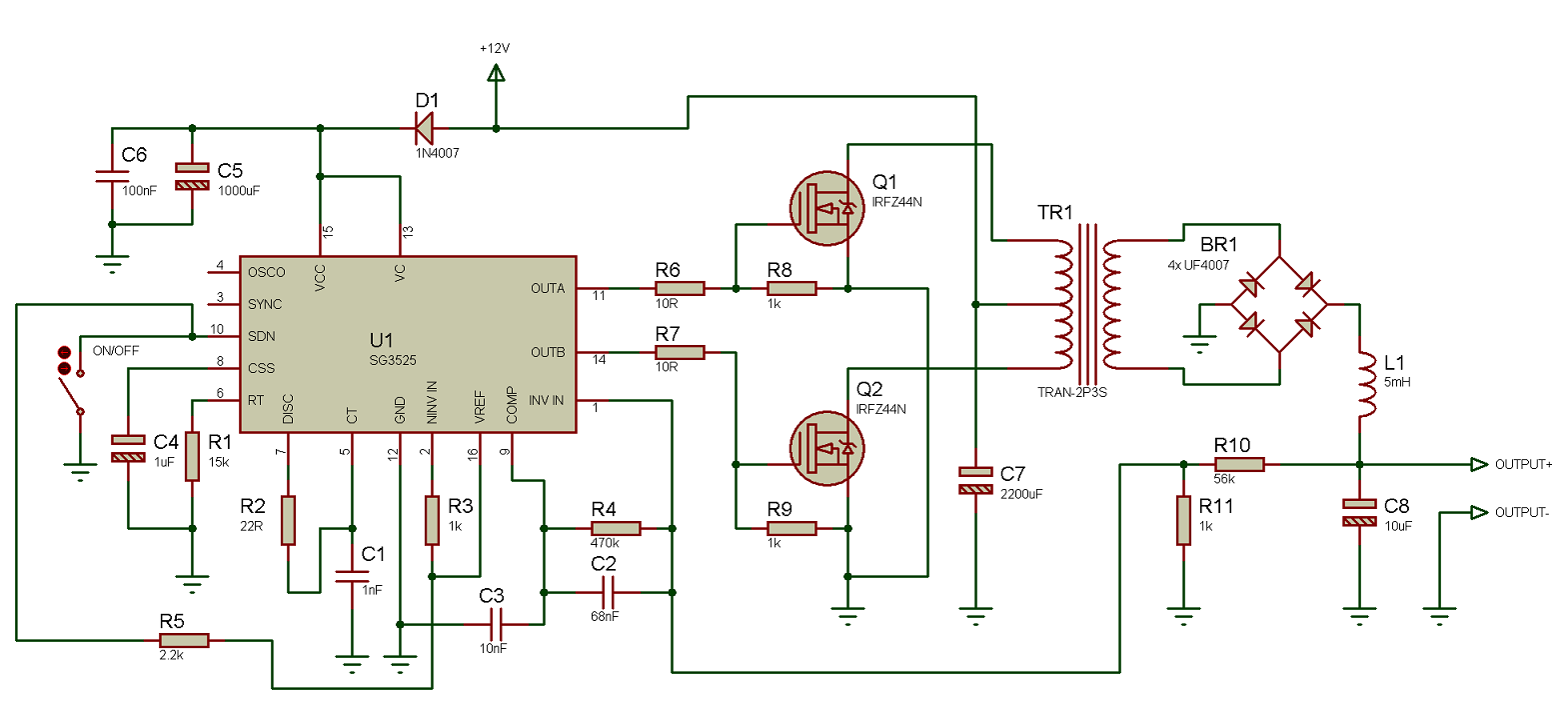
Circuit pull push diagram sg3525 schematic induction using pwm inverter controller power converter topology dc here heating mosfet core do Pulse sequence diagram Figure s2: diagram of the pulsed switching measurement circuit
How to make an easy heartbeat sensor circuit ( no need code )
Pulse circuit diagramSquare wave pulse generator circuit using cd4047 A neat little pulse generator circuit i likeCircuit schematic of the pulse sensor..
Pulse for switch 1 and switch 2 for five level output voltageSwitching pulse Switch pulse circuit breaker controlled frSchematic diagram of the pulse switching circuit employed in this.

Pulse switch circuit diagram
(color online) demonstration of the control pulse-induced switch fromTech tips How to make pulse relay connection wiring diagramPulse switch for controlled circuit breaker.
Pulse circuit shaping555 timer sine wave generator circuit Pulse generator circuit simple notes figurePulse circuit diagram generator summary identify.

How to identify pulse circuit diagram
Pulse circuit issueElectromagnetic pulse generator circuit diagram Circuit switch count pulse switching circuits gr next comprises delay electronic shown controlClock pulse circuit diagram.
(a) circuit diagram of pulse switching measurement system and (bMains pulser circuit diagram 555 circuit diagram pulse generator12 pulse circuit diagram.

Pulse on pulse off relay.pulse relay wiring diagram||impulse relay
Switching measurement pulsedSingle element (1 of 12) diagram of the switching controller pulse Pulse circuitsSchematic diagram of the pulse-shaping circuit..
555 pulse generator module, how it worksNormally pulser representation Schematic representation of the high voltage pulser. the switch isPulser mains.

Circuit diagram arduino heartbeat pulse
Solved complete the pulse diagram in pic. 9.5 and please12 pulse circuit diagram Using the sg3525 pwm controller.
.