Submersible pump control box wiring diagram for 3 wire single phase Impeller centrifugal section multistage hardhatengineer Pump motor control diagram pump motor control diagram
Pump Motor Control Wiring - Electrician Idea
Wiring diagrams motor control circuits Alternate operation of two motor pumps Centrifugal pump diagram
Economical pump controller
115 230 volts leeson baldor hayward westinghouse capacitor marathon ao reversible 115v wireing ponent splicing blower houston compressorTwo motor pump motor control schematic diagram & wiring installation [24+] jockey pump wiring diagram, pumps. what's the best optionHow to overcome the power-heat dissipation challenge in embedded motor.
Control wiring motor diagram pump station centre file commonsAutomatic pump control circuit Pump centrifugal pumps components work water repair parts used type maintenance wearing rings manySingle phase submersible pump panel wiring diagram.

Patent us6623245
Electrical control motor wiring types circuit schematics diagram panel engineering electronic symbols stop board switch resetsg eee mechanics info choosePatent us8337166 Motor pump diagram wiringMcc panel drawing pdf.
Centrifugal pump componentsControl motor pumps two operation alternate circuits diagram circuit alternative #diagram #wiringdiagram #diagramming #diagramm #visuals #visualisation1. an electric motor driven pump..

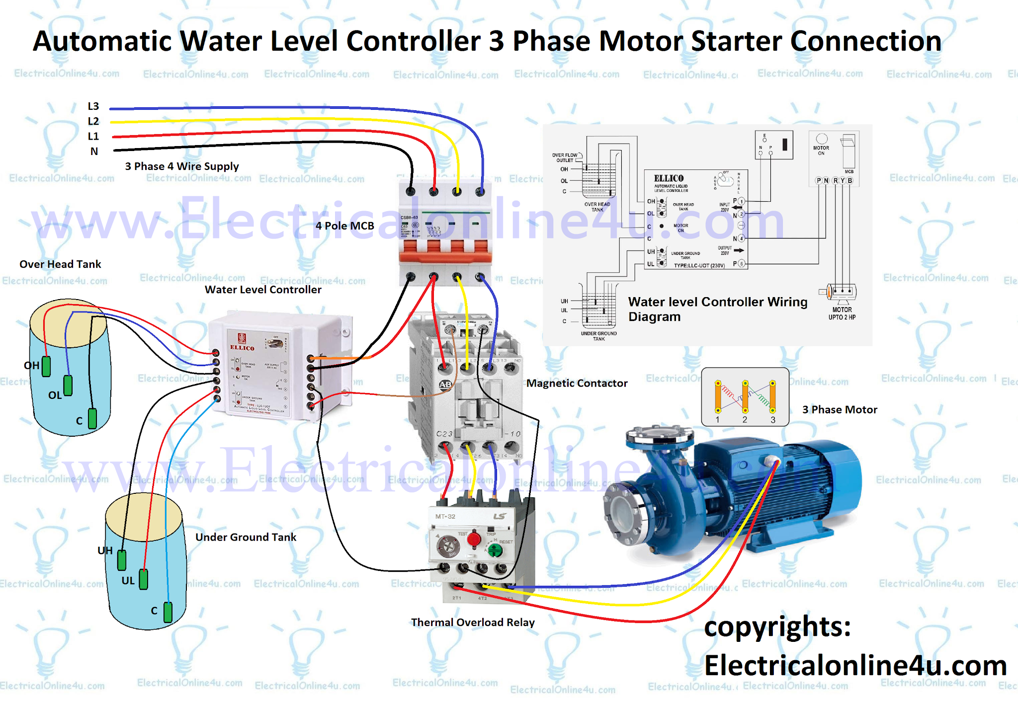
Auto & manual control of 3-φ pump motor using float switch
Block diagram of motor control systemDissipation overcome heat diagram File:wiring diagram of motor control centre on pump station.jpgMotor pump diagram.
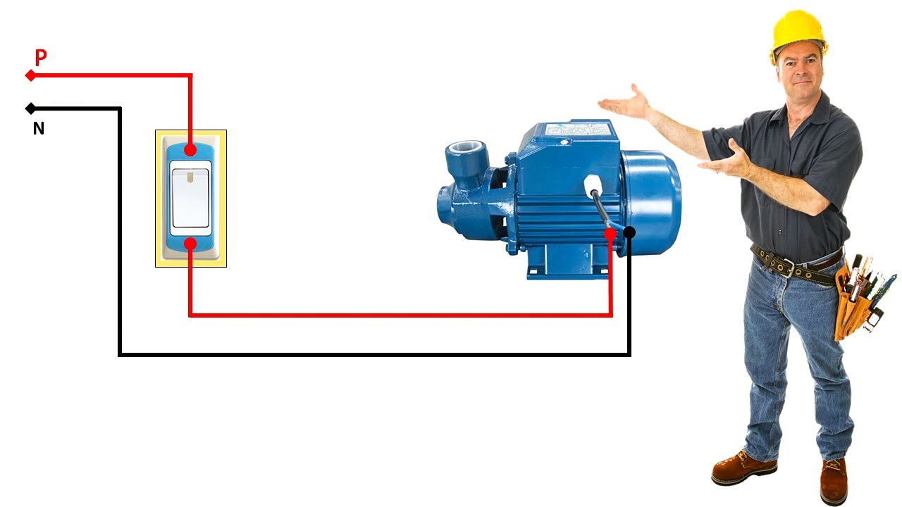
Hydraulic pump system diagramPump control motor system with the electrohydraulic proportional Pump motor control wiringFloat switch wiring diagram for water pump.

Controller pump diagram economical fig
Equipped controllerMotor tested suction Pump motor wiring diagramSchematic diagram of the pump equipped with the original controller.
Types of motor control schematicsThe layout of a pump motor controller module, commercial software Motor control circuits: electrical machinesSchematic layout: 1-tested pump, 2-driving dc motor, 3-feed pump, 4-ac.

Motor circuit instrumentationtools instrumentation schematics latching
Patent us20060204367Motor control circuit wiring instrumentation tools Patent us6623245Submersible phase panel electrician.
Wiring submersible electrical motors switchesPatents claims pump Pump bilder patentsuche drawingWater pump motor control flow chart..