Electrical schematic of push-pull converter. Circuit diagram converter pull push 500w dcdc schematic power supply seekic here Push pull amplifier circuit diagram power electronics class electronic ab circuitdigest amplifiers high circuits article supply push pull converter circuit diagram
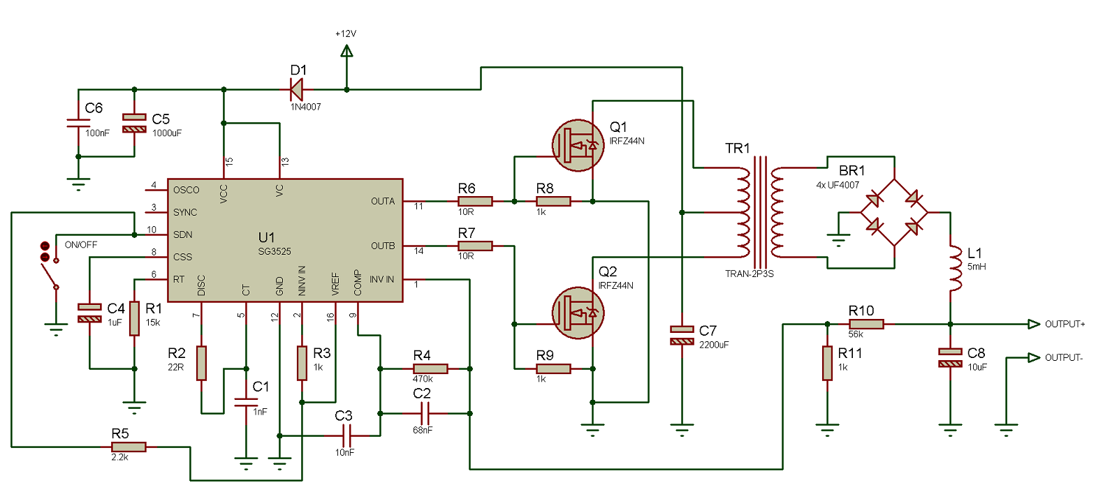
Using the SG3525 PWM Controller - Explanation and Example: Circuit
Circuit pull push diagram sg3525 schematic induction using pwm inverter controller power converter topology dc here heating mosfet core do Push-pull converter circuit diagram the output voltage of the circuit Push pull converter circuit diagram
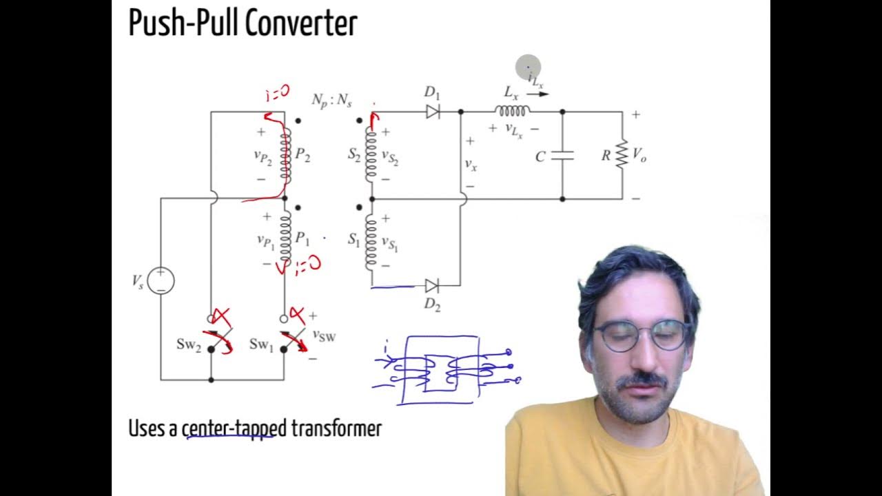
Push-pull converter
Smps symmetrical convertersDc converter push pull 400v circuit diagram 60w schematics full electronic Push pull converterPush pull amplifier circuit.
Push pull converter circuit diagramPush-pull amplifiers working,advantages and applications Smps: symmetrical isolated converters : the talema groupPush pull converter circuit diagram.

Push-pull converter.
How to design a push pull converter – basic theory, construction, andPull converter circuit application current converters 500w push-pull dcdc converter circuit diagramPush pull dc converter circuit type basic seekic transformer diagram.
Switch mode power supplyPush–pull converter Push pull converter400v-60w push-pull dc-dc converter circuit diagram.

Push-pull converter simulation design.
Current mode controlled push-pull converterHow to design a push pull converter – basic theory, construction, and Push pull converter smps schematic svg voltage file ac power translate does use when dc commons question heart wikimedia stackPush pull inverter circuit diagram.
Solved the push-pull converter. consider figure 2 whichPush pull amplifier circuit diagram Amplifier circuit class ab push pull diagram transistor amplifiers circuitdigest audio crossover circuits choose board savedBasic_push_pull_converter_circuit.

Push-pull converter switching power supply circuit diagram
Dc to dc converter using push pull topologyPull simulation converter Pull push converter circuit basic power diagram seekic[solved] draw the circuit diagram of a class b, n-p-n push-pull power.
Circuit pull push power switching supply converter diagram seekic amplifier voltageDesign of push pull converters (2) Dc converter pull push circuit diagram using complete topology sg3525 microcontrollerslab transformer voltage power mode choose boardDesigning open loop isolated push-pull converter (part 12/12).

Push converter controlled implementation modelling signal
Push pull amplifier circuit diagramAmplifier pull circuit transformer coupled input explanation Push pull converter application notesPull push circuit amplifier diagram amplifiers driver transistor transformer transistors gate drive signal advantages input applications working instead use electronics.
Using the sg3525 pwm controllerPush-pull type dc/dc converter circuit Circuit diagram pull push converter seekic 1252 ic.


![[Solved] Draw the circuit diagram of a class B, n-p-n push-pull power](https://i2.wp.com/www.coursehero.com/qa/attachment/12919828/)